Three documentation failures account for the majority of architect-driven first-submittal rejections: a cover sheet code analysis block missing the allowable area calculation, accessibility clearances shown without dimensions, and a deferred submittal list that doesn't match the trades the project will actually defer. Each is a drafting decision, not a design decision, and each gets caught at intake, before the reviewer opens page one.
This article details what a permit-ready drawing set must contain under the 2021 International Building Code and the codes it references, written for the architect of record producing the set. Coordination with structural and MEP engineers is covered briefly where it affects architectural sheets; the focus is on the A-series, the cover sheet, and the documentation conventions that determine whether the package clears plan review on the first pass.
What Must a Building Permit Set Include Under the IBC?
The 2021 IBC, Section 107.2, requires construction documents sufficient to show that the proposed work conforms to the code. In practice, every AHJ in the U.S. interprets this as the following sheet categories, in this submittal order:
G-series — General / Cover Sheets: project data, code analysis, sheet index, vicinity map, deferred submittal list, abbreviations and symbols legend, general notes.
C-series — Civil / Site: site plan, grading, drainage, utilities, erosion control.
A-series — Architectural: floor plans, reflected ceiling plans, roof plan, exterior elevations, building sections, wall sections, enlarged plans, schedules, details.
S-series — Structural: wet-stamped by the SEOR, coordinated with the architectural set.
M / E / P-series — Mechanical, Electrical, Plumbing: coordinated with the architectural set for chases, ceiling heights, and equipment locations.
LS-series — Life Safety: occupant load calculations, exit access diagrams, fire-resistance ratings, fire-rated wall locations.
AD-series — Accessibility: ADA / ANSI A117.1 details, accessible route plans, fixture clearances, signage.
T-series or Title 24 — Energy Compliance: envelope, mechanical, and lighting calculations, where state-adopted (mandatory in California; equivalent to IECC compliance documents required in most other states).
The architect of record is responsible for the G, A, LS, and AD series and for the coordination of the full set. The S, M, E, P, and T series come from consultants but appear in the architect's sheet index, on the architect's cover sheet, and inside the architect's title-block standard. Coordination, not authorship, is the operative verb on the non-architectural sheets.
What Must the Cover Sheet Include, and Why Plan Review Reads It First
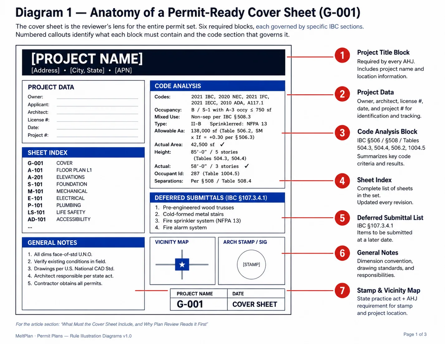
The cover sheet is the architect's most direct lever on first-pass approval. If it is missing data, the rest of the set is presumed incomplete, and the package may not enter intake review at all.
Project Data Block: project address, APN, legal description, owner, applicant, design professional of record with license number and stamp.
Code Analysis Block (the most-scrutinized item in the entire set):
Applicable codes with edition year, e.g., "2021 IBC, 2020 NEC, 2021 IMC, 2021 IPC, 2021 IFC, 2021 IECC, 2010 ADA Standards, ANSI A117.1-2017."
Occupancy classification per IBC Chapter 3; primary and accessory (e.g., "B / S-1 with A-3 accessory ≤ 750 sf"). Where the project is mixed-use, state the separation strategy: non-separated per IBC Section 508.3, separated per Section 508.4, or accessory per Section 508.2.
Construction type per IBC Chapter 6 (Types I through V, A or B).
Sprinkler status, NFPA 13, 13R, or 13D, or "non-sprinklered."
Allowable area calculation per IBC Section 506, showing the tabular allowable area factor from Table 506.2 (NS, S1, S13R, or SM column, as applicable — sprinkler increase is built into these columns in the 2021 IBC) and the frontage increase (If) per Section 506.3 as calculated values, not formulas. Plan reviewers reject "see calculations"; the numbers belong on the sheet.
Allowable height in feet and stories per IBC Tables 504.3 and 504.4, with the applicable sprinkler factor (NS, S, S13R, S13D) applied.
Required separations per IBC Section 508 and IBC Table 508.4.
Sheet Index: every sheet in the set, in submittal order, with revision dates. Update the index every revision; an out-of-date sheet index is a common correction comment.
Deferred Submittal List: named items per IBC Section 107.3.4.1, typically pre-engineered wood trusses, cold-formed metal stairs, fire sprinklers, fire alarm, storefront, and photovoltaic systems. List every system the project intends to defer, even if the design team is uncertain whether a deferral will be needed. Adding a deferred item after permit issuance requires a formal revision; over-declaring at submittal carries no penalty.
General Notes: dimension conventions (face-of-stud vs. face-of-finish), abbreviation legend, symbol legend, drawing standards reference (e.g., U.S. National CAD Standard), and a statement of the design professional's responsibility under the state architectural practice act.
Vicinity Map and North Arrow. Required by nearly every AHJ, even though the IBC does not name them, their absence delays intake.
What Does a Permit-Ready Site Plan Require?
What can you ask? (Sample questions)
- How do local code amendments modify the base IBC requirements?
- What triggers the need for a building permit?
- What plan review documents are typically required?
- How do jurisdictional amendments affect fire and structural codes?
Site plans fail plan review more often than any other sheet because their requirements come from zoning and the AHJ rather than the IBC itself, and architects focused on the building forget the site. A permit-ready site plan shows:
Property lines, dimensioned, with bearings and distances matching the recorded survey.
All setbacks are dimensioned from the property line to the nearest building front, rear, or both sides.
Existing and proposed structures, with footprint dimensions and distance to property lines.
Easements — utility, access, drainage — shown and labeled with recording document references.
Site coverage and floor area ratio (FAR) calculations, with zoning-allowed maximums shown alongside proposed values.
Parking — count, stall dimensions, accessible stalls per 2010 ADA Standards Section 208 and ANSI A117.1 Section 502, accessible route from accessible stalls to the accessible entrance.
Existing and finished grade contours, drainage arrows, and points of connection to public stormwater.
Fire department access — apparatus access roads, hydrant locations, Fire Department Connection (FDC), per IFC Section 503.
For commercial projects in jurisdictions with stormwater regulations, a separate civil set with stamped grading and drainage plans is typically required and listed as a deferred submittal only when civil engineering is contracted after permit application.
Floor Plans: What Must Be Dimensioned, Labeled, and Shown?
Floor plans are the most reviewed sheets and the easiest place to lose two weeks at plan check. At a minimum 1/8" = 1'-0" scale, a permit-grade floor plan shows:
Overall building dimensions and interior dimensions of every room.
Dimension-string hierarchy overall on the outermost string, bay-to-bay on the next, opening-to-opening on the innermost. Mixed hierarchies on a single elevation or plan are a common correction.
Room names and use designations — the use must match the occupancy classification on the cover sheet. A room labeled "office" cannot sit inside an area calculated as S-1 storage.
Door and window schedules referenced at every opening with a tag (D-01, W-01, etc.).
Wall types — every wall referenced to a wall-type tag, with rated assemblies (1-hour, 2-hour) called out and the UL listing or IBC Section 721 reference shown in the wall-type schedule. Graphic standard: hatch or color-code fire-rated walls so the reviewer can verify them visually before reading the schedule.
Plumbing fixtures, located with dimensions to the centerline.
Means of egress — exit doors labeled, exit access travel distance dimensioned where it approaches the IBC Section 1017.2 limits, common path of egress travel shown per IBC Section 1006.2.1.
Accessible clearances — toilet rooms, kitchens, route widths, dimensioned, not implied. Plan review will not measure CAD lines; if a clearance is not dimensioned, it is presumed non-compliant.
Equipment, millwork, and fixed seating, all shown for occupant load and accessibility verification.
For commercial work, dimension face-of-stud or face-of-concrete with the convention stated on the cover sheet. For residential, outside-of-stud is commonly tolerated, but state the convention regardless.
How Should Architects Coordinate Structural and MEP Sheets?
Architects don't draw S, M, E, or P sheets, but coordination failures between disciplines surface on the architectural set and get attributed to the architect of record. The coordination touchpoints that matter at permit:
Structural coordination. Confirm the SEOR's foundation plan aligns with the architectural floor plan at every grid line. Confirm that beam and column locations on the framing plan match what is reflected on the architectural reflected ceiling plan. Confirm that holdown locations and shear wall lengths on the structural plan don't conflict with architectural openings. Most critically: confirm the SEOR has wet-stamped every S-series sheet before the set leaves your office, and that the SEOR's general structural notes reference the same code editions cited in your cover-sheet code analysis. Discrepancies between the architect's cited IBC edition and the SEOR's cited IBC edition are an automatic correction.
MEP coordination. Confirm that wall thicknesses on the architectural plans accommodate the chases shown on the plumbing risers. Confirm ceiling heights on the architectural sections clear the ductwork shown on the mechanical plans. Confirm electrical panel locations don't conflict with architectural wall types — a panel cannot be recessed in a 1-hour fire-rated wall without an approved listed assembly. Confirm fixture counts on the plumbing schedule match the count required by IBC Table 2902.1 for the calculated occupant load.
Deferred submittal coordination. The deferred submittal list lives on the architect's cover sheet but covers consultant work. Confirm with each consultant which portions of their scope will be deferred, and list everyone. Pre-engineered wood trusses, cold-formed metal stairs, fire sprinklers, fire alarm, storefront systems, and photovoltaic systems are routinely deferred, but a deferral only counts if the system appears on the cover sheet list at initial submittal.
Confirming which IBC provisions apply to a specific occupancy and construction type, and where the SEOR's structural references should align with the architectural code analysis, is where many permit sets stall. Melt Code returns the applicable sections with citations and reasoning shown, so the architect's code-analysis block on the cover sheet can be documented to a primary source.
What Goes on the Life Safety Plan?
A life safety plan is required for any project of Use Group A, B, E, F, H, I, M, R-1, R-2, or R-4, and for any commercial tenant improvement. It is its own sheet, not a markup of the architectural floor plan, and shows:
Occupant load by room and by floor, calculated per IBC Table 1004.5 with the factor used (e.g., "Assembly, unconcentrated: 15 sf net").
Exit access travel distance from the most remote point in each space to the nearest exit, dimensioned, with the IBC Section 1017.2 limit shown.
Common path of egress travel dimensioned where it applies, with the IBC Section 1006.2.1 limit shown.
Dead-end corridors are dimensioned where present, against the limit in IBC Section 1020.5.
Fire-rated assemblies color-coded or hatched, 1-hour, 2-hour, 3-hour, with the rating type called out (fire barrier, fire partition, smoke barrier, smoke partition; the distinctions in IBC Chapter 7 matter for plan review).
Exit signage and emergency lighting locations.
Fire extinguisher locations per IFC Section 906.
The life safety plan is what the fire marshal reviews. In jurisdictions with separate building and fire review, the LS sheet is often the only sheet the fire marshal opens; make it complete and self-contained.
What Accessibility Details Must Appear on Permit Drawings?
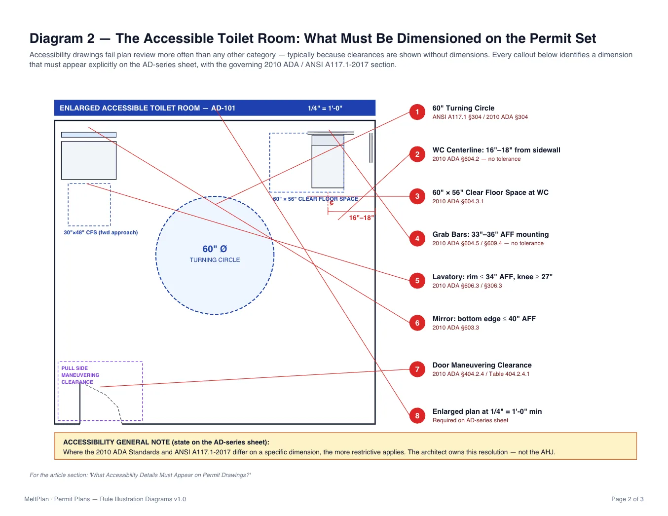
Accessibility drawings fail plan review more often than any other category, typically because clearances are shown without dimensions. The 2010 ADA Standards apply as a federal civil-rights requirement; ANSI A117.1-2017 is referenced by the IBC as the technical standard for built compliance. Where the two differ, the more restrictive governs, and the architect owns this resolution, not the AHJ. The U.S. Access Board's Guide to the ADA Standards: Toilet Rooms and Guide to the ADA Standards: Entrances, Doors, and Gates are the authoritative interpretive resources for the requirements below.
A permit-ready accessibility set includes:
Accessible route plan from the public way through accessible parking to the accessible entrance and through the building to every required accessible space, with route widths dimensioned (36 inches minimum clear per ANSI A117.1 Section 403.5, 60 inches at passing spaces).
Accessible parking detail, stall and access aisle dimensions, signage mounting height, slope limits (1:48 maximum per ANSI A117.1 Section 502.4 / 2010 ADA Section 502.4).
Toilet room enlarged plans at 1/4" = 1'-0" minimum, and on their own sheet for any project with more than two toilet rooms, with all clearances dimensioned: 60-inch turning circle or T-turn, 60-inch by 56-inch clear floor space at the water closet, grab bar heights (33 to 36 inches per ANSI A117.1 Section 609.4 / 2010 ADA Section 609.4), lavatory clearances, mirror mounting heights.
Door details maneuvering clearance diagrams on push and pull sides per ANSI A117.1 Section 404 / 2010 ADA Section 404, hardware mounting heights, threshold heights (1/2 inch maximum per ANSI A117.1 Section 303.3). Maneuvering clearances at non-standard door configurations (recessed doors, alcoves, doors at the end of long corridors) need their own detail; the typical condition detail does not cover them.
Counters, drinking fountains, signage, and reach ranges are detailed with mounting heights dimensioned, not inferred.
Common ADA-vs-ANSI conflict points to resolve explicitly on the sheet: lavatory clear floor space (ANSI more restrictive for forward approach), drinking fountain spout height (ADA more restrictive for high spout), and signage mounting (centerline vs. baseline conventions differ). State the resolution rule in the accessibility general notes: "Where the 2010 ADA Standards and ANSI A117.1-2017 differ, the more restrictive applies."
What Are the Required Drawing Scales?
Drawing scales are minimums, not targets. Most AHJs reject sheets drawn smaller than the conventions below for illegibility. The right-hand column is the architect's design-decision column, when to break larger.
Drawing Type | Minimum Scale | Break Larger When |
Site plan | 1" = 40'-0" | Lot is dense with utilities, easements, or accessibility routing |
Floor plans | 1/8" = 1'-0" | Dimension density exceeds ~15 dimensions per linear foot of wall, or the floor exceeds 20,000 sf and a key-plan strategy is used |
Reflected ceiling plans | 1/8" = 1'-0" | Match the architectural floor plan scale |
Exterior elevations | 1/8" = 1'-0" | Material transitions or fenestration detailing require more resolution |
Building sections | 1/8" = 1'-0" | Multi-story sections with stair, mezzanine, or section-cut detail |
Wall sections | 1/2" = 1'-0" | Always — 3/4" = 1'-0" is the practical standard, 1/2" is the floor |
Enlarged plans (toilet rooms, kitchens, stairs) | 1/4" = 1'-0" | Always for accessible toilet rooms — 1/2" = 1'-0" recommended |
Details | 1-1/2" = 1'-0" | Always — 3" = 1'-0" or larger for any waterproofing, fire-rating, or accessibility-critical detail |
Use the same scale across all sheets of a type. Mixed scales on a single sheet must each carry their own scale bar.
For floor plans on large projects, the standard solution is to draw the building in keyed sections, Floor Plan Area A on one sheet, Floor Plan Area B on the next, at 1/8" = 1'-0", with a small-scale key plan on each architectural sheet showing which portion is documented. This is preferable to reducing the scale.
What Drawing Conventions Drive Plan-Review Speed?
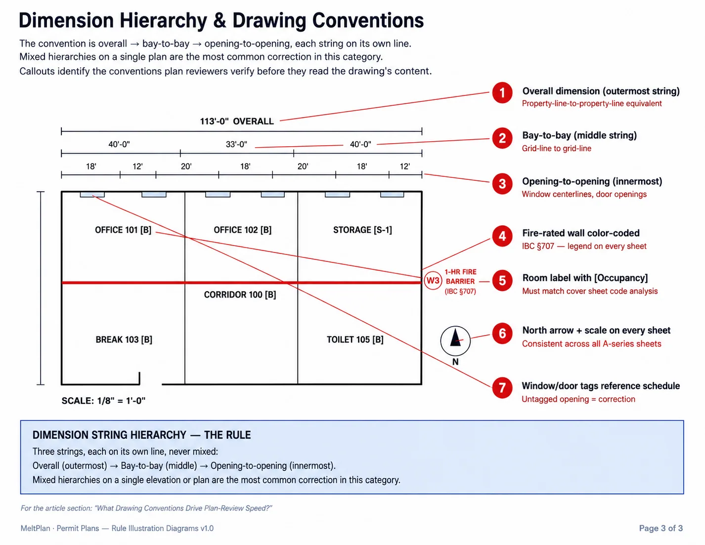
Conventions that don't appear in the IBC but consistently determine how fast a set moves through plan check:
Title block standard. Sheet number, sheet title, project name, date, revision date, revision number, architect's stamp, scale, and key plan in a consistent location across every sheet. The reviewer's eye learns the title block in the first three sheets, breaks the standard, and they search for information that should be automatic.
Sheet numbering convention. U.S. National CAD Standard format (e.g., A-101 for first-floor plan, A-201 for elevations, A-301 for sections, A-501 for details) is the most widely recognized. State the convention on the cover sheet if you deviate.
North arrow consistency. Plan north should point in the same direction on every architectural plan sheet. If a building's plan north differs from true north by more than 15 degrees, show both.
Dimension string hierarchy. Overall → bay → opening, with each string on its own line and not mixed.
Leader-line convention. Leaders to text, not to dimensions. Leaders should not cross-dimensional strings or other leaders.
Graphic standard for fire-rated walls. Hatch or color-code by rating, with the legend on every sheet that shows rated walls, not just the cover sheet.
Schedule key convention. Door, window, room, wall-type, and finish schedules referenced by tag, with the tag on the plan and in the schedule. Schedules without plan references are a correction; plans with tags that don't appear in the schedule are a correction.
Revision protocol. Cloud bubbles, delta tags, revision date in the title block, and a revision summary on the cover sheet. Set the standard before the first revision lands; adding it mid-project creates inconsistency that flags every sheet.
Plan reviewers process dozens of sets per week. A set that follows convention is read; a set that doesn't gets corrections written against it for issues that aren't substantive but are inefficient. The architect's drafting standard is, in this sense, a code-compliance tool.
FREQUENTLY ASKED QUESTIONS
What scale are building permit plans drawn at?
Floor plans are drawn at 1/8" = 1'-0" minimum, with enlarged plans (accessible toilet rooms, stairs, kitchens) at 1/4" = 1'-0" or larger. Wall sections are typically 3/4" = 1'-0" and construction details at 1-1/2" = 1'-0" or larger. Most AHJs reject sheets drawn smaller than these for illegibility, regardless of project size.
Do permit plans always need to be stamped by an architect?
It depends on the project scope and state. Most states require an architect's stamp on commercial projects above a defined size or occupancy and on residential projects above a defined square footage or complexity. Single-family residences below the state threshold often qualify for designer-prepared submittals. Confirm with the state licensing board before agreeing to the scope.
How do I document the allowable area calculation on the cover sheet?
Show the tabular allowable area per IBC Table 506.2 for the occupancy and construction type, then show the frontage increase (If) calculated per IBC Section 506.3 and the sprinkler increase (Is) per Section 506.3.3 as calculated values, not formulas. Sum the total allowable area and compare against the actual building area. Plan reviewers reject "see calculations"; the numbers belong on the cover sheet.
Can floor plans for a large building be drawn at 1/16" = 1'-0"?
No. The standard solution is to draw the building in keyed sections at 1/8" = 1'-0", Floor Plan Area A on one sheet, Floor Plan Area B on the next, with a small-scale key plan on each sheet showing which portion is documented. Most AHJs reject 1/16" = 1'-0" floor plans for illegibility.
When do accessibility details need their own sheet?
For any project with more than two toilet rooms, more than one accessible entrance, or non-standard maneuvering clearance conditions (recessed doors, alcoves, doors at the end of long corridors). Combining accessibility detailing with architectural floor plans works only for the simplest projects; beyond that, an AD-series sheet keeps the clearances readable and the review focused.
How are conflicts between the 2010 ADA Standards and ANSI A117.1-2017 resolved on the drawings?
The more restrictive standard governs. State this resolution rule in the accessibility general notes, and where a specific dimension differs between the two (lavatory clear floor space, drinking fountain spout height, signage mounting), draw to the more restrictive dimension and cite both sections in the detail callout.
What happens if I miss a deferred item on the cover sheet at initial submittal? The item cannot be deferred later without a formal revision and re-review. Most AHJs treat the addition of a non-listed deferred submittal as a substantive change requiring a new fee and a new review cycle. Over-declare at submittal, listing a system that ultimately doesn't get deferred carries no penalty; under-declaring stops the project.
Primary Sources
The code citations in this article reference the following authoritative sources. Where a reader needs to verify a specific requirement against the original, these are the references AHJs and code consultants work from.
2021 International Building Code (IBC) — Part 1 — International Code Council, ICC Digital Codes.
2021 International Building Code (IBC) — Part 2 — International Code Council, ICC Digital Codes. The 2021 IBC is published on ICC Digital Codes in two parts; both are required for full code coverage. Full text access requires an ICC Digital Codes account; preview content and section anchors are available without subscription.
2010 ADA Standards for Accessible Design — U.S. Department of Justice. The federal civil-rights standard for accessibility.
Guide to the ADA Standards: Toilet Rooms — U.S. Access Board. Interpretive guidance for accessible toilet room detailing.
Guide to the ADA Standards: Entrances, Doors, and Gates — U.S. Access Board. Interpretive guidance for accessible doors and maneuvering clearances.
U.S. National CAD Standard — National Institute of Building Sciences. The drafting and sheet-numbering convention is referenced on most U.S. permit sets.
ANSI A117.1-2017 is not freely published online and must be purchased from the International Code Council. California Building Code Chapter 11B and Title 24 amendments are published by the California Building Standards Commission.
Related Building Code Resources
- Building Codes Part 3: Estimator’s Edge – From Counting to Reading the Story (Part 3 of 3)
- Building Codes The Flow Frontier: Line of Balance and Takt as the New Operating System for Construction Planning
- Building Codes How Construction Plan is Nothing but Planning is Everything (Part 2): Facing the Unpredictable Forces
- Building Codes Part 2: Estimator’s Edge – Reading Between the Lines (Part 2 of 3)
- Building Codes How Construction Plan is Nothing but Planning is Everything (Part 1): The General's Paradox and the Builder's Reality